A Screw In Thread is a helical ridge formed on the inside or outside of a cylindrical part. It allows two components to join through controlled rotation. You can see this principle in bolts, machine screws, pipe fittings, and threaded inserts. The thread’s sloping surface converts turning force into forward movement. Simple, but remarkably effective.
When a screw enters a matching internal thread, its crest follows the receiving groove. The screw advances by one pitch during each full revolution. Pitch means the distance between neighboring thread crests. A finer pitch provides smaller movement and can improve adjustment accuracy. A coarser pitch usually engages faster and handles dirt more reliably. The correct fit depends on diameter, pitch, thread profile, material, and intended load.
Force travels through the contact surfaces. Tightening creates clamping force between the joined parts. Friction then helps resist unwanted rotation, although friction is not a perfect locking method. Vibration, poor alignment, damaged threads, or excessive torque can weaken the connection. Small details matter.
In practical work, inspect the thread under bright light before assembly. Look for flattened crests, metal chips, corrosion, or cross-threading. Start the screw by hand, keeping it aligned with the hole. If resistance appears immediately, stop and check the fit. Tools can hide mistakes.
The term “Screw In Thread” is sometimes used loosely. Technical drawings usually specify internal or external threads more precisely. That distinction matters when selecting taps, dies, fasteners, or replacement parts. A basic explanation may overlook lubrication, temperature, and material expansion. Real assemblies are less forgiving than diagrams. Understanding how the thread works helps users choose safer, stronger, and more dependable connections.
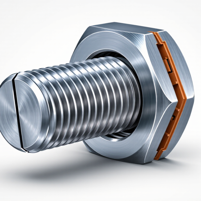
What Is Screw In Thread and How Does It Work?
A screw thread is a continuous helical ridge formed around a cylindrical or tapered surface. Its basic structure includes the crest, root, and flanks. The crest is the raised outer edge, while the root is the recessed valley. Flanks connect them and transfer most of the working load. ISO 68-1 defines the basic metric thread profile with a 60-degree flank angle. ISO 724 specifies fundamental dimensions, including major diameter, minor diameter, and pitch. Pitch means the distance between matching points on nearby threads. In simple terms, the thread is an inclined plane wrapped around a cylinder.
A screw works through controlled rotation and axial movement. When the external thread enters an internal thread, the matching flanks guide the parts together. Torque creates tension in the screw, producing clamping force between the joined surfaces. A finer pitch gives smaller movement per turn and can improve adjustment accuracy. A coarse pitch usually assembles faster and tolerates surface contamination better. ASME B1.1 provides dimensional requirements for unified inch screw threads. These standards support inspection, but real assemblies are less perfect. Surface damage, misalignment, and lubrication can change the result.
Tips: Check pitch with a gauge, not appearance alone. Measure the major diameter at several points. Keep the threads clean and lightly lubricated when specified. Do not assume a similar thread will fit safely. A thread can look correct and still strip under load. Minor errors matter.
What Is Screw In Thread and How Does It Work?
How Thread Geometry Creates Mechanical Engagement
A screw thread is a continuous ridge wrapped around a cylindrical or tapered surface. Its geometry turns rotation into controlled linear movement. As the screw turns, the helical ridge advances through the matching internal thread. This action draws parts together or pushes them apart. Pitch controls travel per revolution. A finer pitch moves less distance but offers more adjustment. A coarse pitch usually assembles faster and tolerates minor debris better.
The real holding force comes from contact between mating flanks, not from the thread tips. Tightening creates preload, which stretches the screw and compresses the joined parts. Friction along the flanks and beneath the head helps resist loosening. Flank angle, thread depth, diameter, and material strength all influence performance. A sharp, damaged crest may look acceptable yet carry little useful load. Small details matter.
In workshop inspections, I check engagement length, surface damage, alignment, and unwanted gaps. A clean fit is reassuring, but it does not prove correct preload. Torque can be misleading when corrosion, lubrication, or rough surfaces change friction. That is where practical judgment becomes important. I have seen properly sized threads fail because the joint was misaligned. The design may be sound. The installation still was not. A reliable connection needs suitable geometry, compatible materials, adequate engagement, and a verified tightening method.
A screw thread is a helical ridge wrapped around a shaft or inside a hole. It changes rotary motion into controlled linear movement. The process begins when the external thread meets the internal thread at the correct angle. Keep it straight. A slight tilt can damage the first turns and create cross-threading.
As the screw rotates, each ridge travels along its matching groove. The pitch determines how far the screw advances during one complete turn. Fine threads move more slowly but can provide precise adjustment. Coarse threads engage faster and often tolerate minor dirt better. As the head reaches the surface, turning creates clamping force between the connected parts. This force is called preload.
Friction under the head and between the threads helps hold the assembly in place. Feel the resistance. If rotation suddenly becomes tight, stop and inspect the alignment. Forcing the screw may flatten the ridges or weaken the material. Lubrication can reduce friction, so the same torque may produce different clamping force. That detail matters. In practical work, torque calculations are useful, but they are not perfect. Surface condition, thread wear, and material hardness can change the result. A careful installation checks thread condition, engagement depth, and final seating before operation.
Screw threads are inclined ridges that convert turning force into clamping force. Their shape, pitch, and direction determine how a fastener enters a hole and resists movement. ISO 68-1 defines basic thread profiles, while ISO 965 controls metric thread dimensions and tolerances. These standards reduce costly mismatches during production.
Metric threads, such as M8 × 1.25, are common in machinery, vehicles, and electronic enclosures. The first number shows diameter; the second shows pitch. Coarse threads assemble quickly and tolerate minor dirt. Fine threads offer better adjustment and stronger holding in thin materials. Unified inch threads use UNC for general fastening and UNF where finer control matters. Pipe threads serve another purpose. NPT threads create a tapered seal in compressed-air, water, and hydraulic connections, following ASME B1.20.1.
A 2024 industrial fastener market report estimates global demand will grow at roughly 4% annually through the decade. That growth reflects construction, transport, and equipment maintenance. However, market volume does not prove technical suitability. A common mistake is selecting thread size before checking load, material, temperature, and sealing needs. I have seen fine threads chosen for dirty workshop environments, where cleaning becomes frustrating. Small details matter. Thread engagement should generally provide enough contact for the applied load, but exact requirements depend on material and engineering calculations. Surface damage, cross-threading, and mixed standards can quietly weaken an assembly. Better practice means checking the drawing, measuring pitch, and confirming the applicable standard before installation.
| Thread Type | Standard or Naming System | Basic Profile | Typical Included Angle | How It Works | Common Practical Uses | Strengths | Important Considerations |
|---|---|---|---|---|---|---|---|
| ISO Metric Coarse | M designation; diameter in millimetres, followed by pitch when needed, such as M10 × 1.5 | Symmetrical V-shaped thread with a flat or slightly truncated crest and root | 60° | The inclined thread surfaces convert tightening torque into axial clamping force between mating parts. | General-purpose bolts, nuts, machine frames, automotive assemblies, equipment housings, and structural connections | Widely standardized; relatively fast assembly; greater depth than fine threads for the same nominal diameter | Coarse threads are generally more tolerant of dirt and minor damage, but they provide less pitch-based adjustment than fine threads. |
| ISO Metric Fine | M designation with a smaller pitch, such as M10 × 1.25 | Symmetrical 60° V-shaped profile with closer thread spacing than a coarse thread | 60° | More threads engage over a given length, allowing smaller axial movement per revolution and finer adjustment. | Thin-wall components, automotive and machinery adjustments, hydraulic fittings, and applications requiring precise tension control | Improved adjustment resolution; larger minor diameter can provide a relatively greater tensile stress area for the same nominal diameter | More susceptible to cross-threading, contamination, and damage during handling; adequate engagement length is important. |
| Unified Coarse | UNC designation; inch-based thread series | Symmetrical V-shaped machine thread | 60° | Matching external and internal threads create friction and clamping force when the fastener is tightened. | General-purpose inch-based machinery, maintenance work, fabricated equipment, and structural fastening | Good general-purpose performance; coarse pitch supports quick assembly and reasonable tolerance to contamination | Must not be interchanged with metric or other inch thread systems, even when the diameters appear similar. |
| Unified Fine | UNF designation; inch-based fine thread series | Symmetrical V-shaped machine thread with a finer pitch than UNC | 60° | The finer pitch increases the number of engaged threads and provides smaller axial movement for each turn. | Precision machinery, instruments, thin sections, vibration-sensitive assemblies, and applications requiring fine adjustment | Fine adjustment; often useful where a larger core diameter or higher clamping control is desirable | Requires cleaner threads and careful alignment; fine threads can be more vulnerable to galling or damage. |
| Acme | Acme thread form; commonly specified by diameter and threads per inch | Trapezoidal profile with broad, flat flanks | 29° included angle | The broad flanks transmit axial load while the larger root section improves durability compared with a sharp V-thread. | Lead screws, machine-tool slides, lifting mechanisms, vises, clamps, and linear positioning systems | Strong, durable, and easier to manufacture than some precision power-thread forms; suitable for repeated motion | Not primarily intended for pressure sealing; lubrication and backlash control may be required in precision systems. |
| Square | Square thread form | Thread sides are approximately perpendicular to the screw axis | Approximately 0° flank angle | Load is transferred almost directly along the flanks, reducing radial components and improving mechanical efficiency. | Older or specialized screw jacks, presses, actuators, and high-efficiency power transmission mechanisms | Very efficient for transmitting motion and axial load; low wedging effect | More difficult to manufacture, inspect, and repair than Acme or trapezoidal threads; less common in general-purpose products. |
| Buttress | Buttress thread form | One nearly vertical load flank and one angled backing flank | Varies by standard and design | The steep load flank carries high axial force in one preferred direction, while the angled flank supports return movement. | Heavy-duty presses, jacks, clamps, large valves, and mechanisms with predominantly one-directional loading | High load capacity in one direction; efficient for unidirectional axial forces | Performance is direction-dependent; correct orientation and matching components are essential. |
| Tapered Pipe Thread | Examples include NPT and ISO 7-1 tapered pipe threads | Usually a tapered V-shaped thread; the outside diameter changes along the threaded length | Common forms use a 60° or 55° profile, depending on the standard | As the male and female tapered surfaces tighten, interference between the flanks helps create a pressure-resistant joint. | Low- and medium-pressure piping for air, water, oil, gas, and general process connections, when permitted by the applicable standard | Can provide mechanical engagement and sealing in one threaded connection | Thread sealant is often required; standards with different angles, pitches, or taper rates must not be mixed. |
| Parallel Pipe Thread | Examples include ISO 228 and parallel pipe-thread forms used with separate sealing elements | Constant outside diameter along the threaded portion | Depends on the applicable standard; many pipe forms use a 55° profile | The threads provide mechanical fastening, while a gasket, O-ring, bonded washer, or other sealing element performs the primary sealing function. | Hydraulic and pneumatic ports, instrumentation, fittings, and serviceable pipe connections | Good repeatability; sealing components can be replaced without relying on thread interference | Thread compatibility alone does not guarantee sealing; the correct seal, port geometry, and tightening method are required. |
| Self-Tapping Screw Thread | Application-based screw form rather than one single universal standard | Sharp or modified thread designed to form or cut mating material during installation | Varies by screw design | The screw displaces or removes material in a prepared hole, creating internal threads as it advances. | Sheet metal, plastics, wood-based panels, light assemblies, and applications where a separate nut is unnecessary | Fast installation; can reduce component count and assembly cost | Pilot-hole size, material thickness, installation torque, and thread-forming capability must be matched to the workpiece. |
| Self-Drilling Screw Thread | Self-drilling screw design with an integrated drill-point tip | Threaded shank combined with a cutting point that creates its own pilot hole | Varies by design | The drill point penetrates the material first, followed by thread formation or engagement as the screw advances. | Sheet-metal installation, light-gauge steel framing, roofing-related assemblies, and enclosure work | Can combine drilling and fastening in one operation; reduces preliminary drilling steps | Material thickness, point capacity, driver speed, and corrosion protection must suit the application. |
| Wood Screw Thread | Wood-screw design; dimensions vary by applicable product standard | Typically a deep, relatively coarse thread with a sharp point and cutting geometry | Varies by design | The pointed tip starts the hole and the coarse threads develop holding force by engaging wood fibres or engineered wood. | Timber, plywood, particleboard, furniture, cabinetry, and general woodworking | Good grip in fibrous materials; many designs allow installation with a pre-drilled pilot hole | Pilot-hole size and depth affect splitting, pull-out resistance, and installation torque; wood moisture and density also matter. |
What Is Screw In Thread and How Does It Work?
A screw thread is a helical ridge that converts rotation into controlled linear force. Its strength depends on more than thread diameter. Material strength, pitch, engagement length, and root geometry all affect performance. A fine pitch can improve adjustment and load distribution. However, it may be more sensitive to damage and contamination. Coarse threads usually tolerate rough handling better.
Preload is often the decisive factor. It clamps the joint before service loads act on the screw. NASA’s Fastener Design Manual, NASA RP-1228, commonly discusses preload targets near 75% of proof strength for suitable preloaded joints. This value is not universal. Temperature, fatigue, reused hardware, and joint stiffness can change the safe limit. Torque alone is an imperfect control method. Friction under the head and inside the threads can consume most of the applied torque. In practical assembly checks, the same torque may produce very different clamp forces.
Thread engagement also matters. One diameter of engagement is often used as an initial guideline for steel joints, but it cannot replace calculation. Softer materials may require longer engagement or inserts. VDI 2230 Part 1 evaluates bolt preload, friction, external loads, and fatigue together. Misalignment remains an overlooked problem. Even a strong screw can fail when the joint bends it sideways. Corrosion is quieter, but equally serious. A clean drawing is not proof of a durable connection. The design still deserves testing under real vibration, temperature, and installation conditions.
Key Factors Affecting Thread Strength and Performance
This chart compares the tensile stress area of common coarse-pitch ISO metric threads. A larger tensile stress area generally allows a screw to carry greater axial load. The values are based on nominal thread geometry; actual performance also depends on material grade, preload, engagement length, friction, tightening accuracy, and thread quality.
A screw thread is a helical ridge around a shaft or inside a hole. It converts rotation into controlled linear movement. Simple, but precise.
Matching ridges and grooves contact along their flanks. Turning the screw draws parts together or pushes them apart. The thread tips provide little useful support.
Pitch is the distance moved during one complete turn. Fine threads move less per revolution and allow careful adjustment. Coarse threads assemble faster and tolerate small amounts of dirt.
Preload is the clamping force created during tightening. The screw stretches slightly, while the connected parts compress. This helps the joint resist movement during service.
Not always. Lubrication, corrosion, rough surfaces, and wear can change friction. The same torque may create different clamping forces. Torque is useful, but imperfect.
One thread diameter is often an initial guideline for steel joints. It is not a universal rule. Softer materials may need deeper engagement or reinforcement.
The screw should enter straight and smoothly. A slight tilt can damage the first threads and cause cross-threading. Stop there. Do not force it.
Check thread damage, engagement length, alignment, surface gaps, and final seating. Look for flattened ridges or unusual resistance. A clean appearance does not prove correct preload.
A Screw In Thread is a helical ridge formed around the inside or outside of a cylindrical surface, designed to create a secure mechanical connection. Its basic structure includes the crest, root, flank, and pitch, while the thread angle and diameter determine how mating parts fit together. When a threaded fastener is turned, its spiral geometry converts rotational motion into linear movement. The matching ridges engage, distribute contact pressure, and generate clamping force that holds components firmly in place.
Different thread types are suited to different applications, including general fastening, fine adjustment, motion transfer, and resistance to loosening. Thread performance depends on factors such as material strength, thread depth, pitch, alignment, surface condition, lubrication, and applied load. Properly selected and manufactured threads improve durability, assembly efficiency, and connection reliability, while excessive force, poor fit, or damaged surfaces can reduce strength and cause premature failure.

Dongshuo